Design a Synchronous Counter Using Jk Flip-flop
Home » Digital Electronics
Designing of Synchronous Counters
In this article, we are going to learn about the need for designing Synchronous Counters, its procedure of designing, their working, and how its output waveforms can be drawn.
Submitted by Saurabh Gupta, on March 26, 2021
Need for Designing Synchronous Counters
In our last article, Designing of Asynchronous Counters, we studied how can we design asynchronous counters, those counters were connected in series to each other, and clock pulses were not supplied simultaneously to each flip-flop, thus the counter outputs resulted in a delay which was equal to the sum of delays of individual flip-flops. Although it is easier to design an asynchronous counter, because of its limitations such as delay and speed, we started designing synchronous counters. Synchronous counters overcome the limitation of delay and speed as clock pulses are supplied simultaneously to each individual flip-flop. Thus, the transition of clock pulses occurs simultaneously in each flip-flop which helps in the reduction of delay of the counter. Like asynchronous counters, synchronous counters can also be designed using JK, D, or T flip-flops.
Designing of 3-bit synchronous binary up-counter or Mod-8 Synchronous Counter
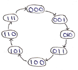
A 3-bit up counter goes through states from 0 to 7, we can draw a state diagram that represents the states, during its working. It is shown as:
State diagram:
As it is a synchronous counter, an external clock is connected to each of the flip-flops present in the counter simultaneously. A logic circuit of the 3-bit synchronous up counter made using negative edge-triggered JK flip-flop is shown below figure:
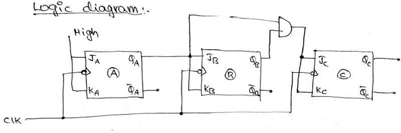
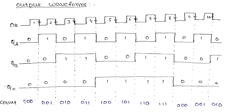
A high input (1) is provided to JA and KA and JB and KB are provided with input QA and inputs to JC = KC = QA . QB. Counter produces the output from QC , QB, and QA in which QC is the MSB, and QA is the LSB. An output waveform can be drawn to understand its working more clearly which can be shown as:
Designing of Synchronous Mod-N Counters
To design a synchronous Mod-N counter, where the value of N need not be always equal to the power of 2, for example, we may need to draw a Mod-5, Mod-7, Mod-10 counter. So, the following procedure needs to be followed for the designing of synchronous counters for any mod-N counter:
Step 1: Determine the number of flip-flops.
The number of flip-flops required to design a mod-N synchronous counter can be determined by using the equation 2n >= N, where n is no. of flip-flops and N is Mod number.
Step 2: Determine the type of flip-flop required.
Step 3: Draw the state diagram which demonstrates the states which the counter undergoes.
Step 4: Using the excitation table of the flip-flop, obtain the flip-flop inputs for each state which were obtained in the second step, and enter them in a table. The flip-flop inputs, that are capable of producing the next state of the counter from the present state, are entered in the table.
Step 5: Make a K-Map for each input combination and simplify it to obtain the minimal Boolean expression for each flip-flop input.
Step 6: Using the Boolean expressions obtained in step 5, draw the required counter circuit by connecting the flip-flops and other gates as per the obtained Boolean expression.
ADVERTISEMENT
Comments and Discussions!
ADVERTISEMENT
Design a Synchronous Counter Using Jk Flip-flop
Source: https://www.includehelp.com/basics/designing-of-synchronous-counters.aspx
0 Response to "Design a Synchronous Counter Using Jk Flip-flop"
Post a Comment